Robotbit Edu Coding with MakeCode
Robotbit Edu can be programmed using Microsoft MakeCode.
Makecode Coding

Loading the extension for Robotbit
1. In the extensions page, search for “KittenBot” or “Robotbit”.
Robotbit Edu and its extension has been officially approved by Microsoft.
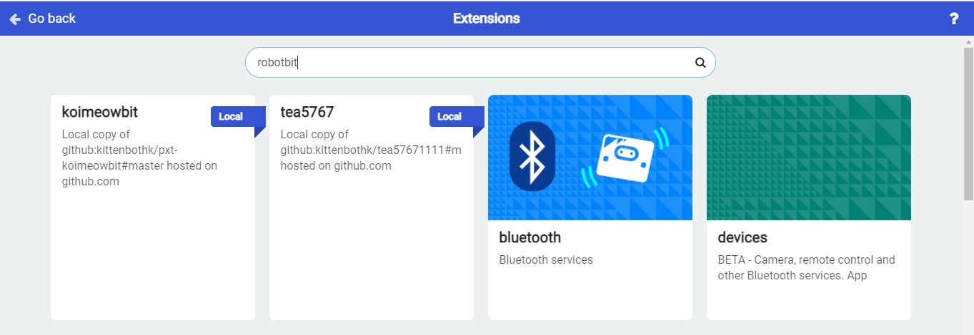
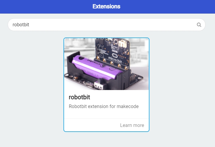
2. In Offline MakeCode by Kittenbot, the Robotbit extension can even be loaded without access to the internet.)
The blocks for Robotbit Edu is added
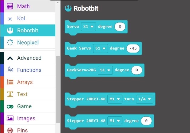
1. Programming Motors
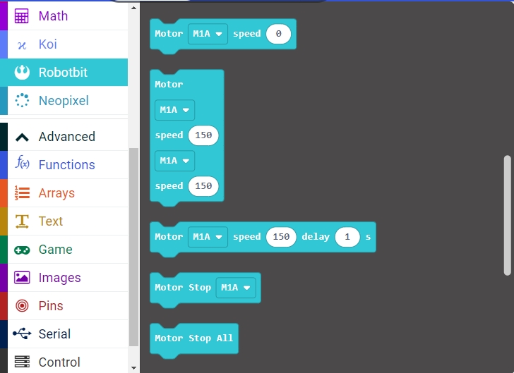
For information about DC motors by Kittenbot, please visit: Kittenbot Actuators
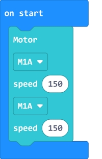
Sample Program:
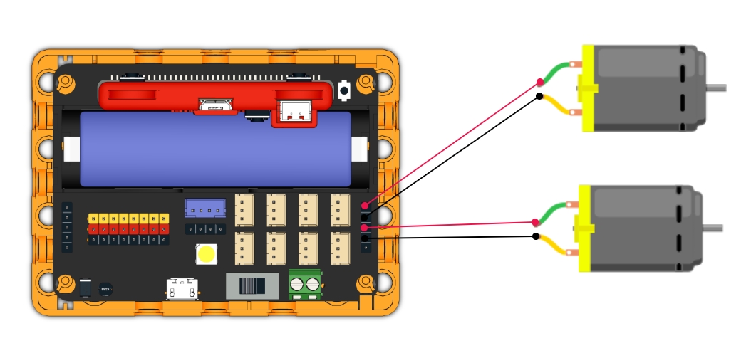
Connect 2 DC motors to the M1A and M1B port of the Robotbit Edu.
2. Programming Servos
For information about servos by Kittenbot, please visit: Kittenbot Actuators
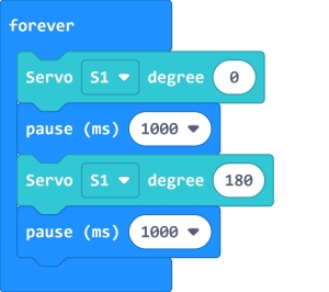
Sample Program:
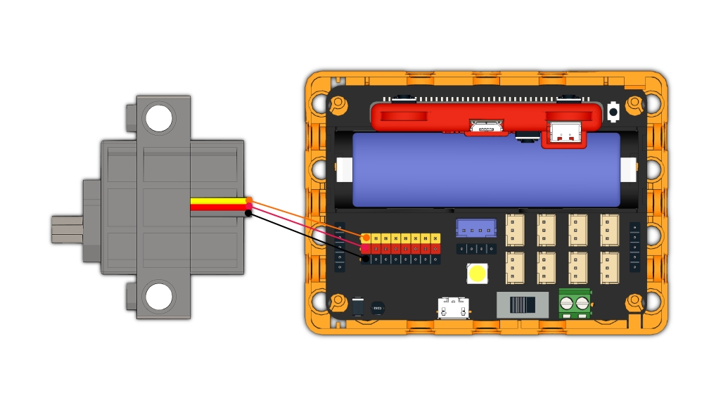
Connect a servo to the S1 port of Robotbit Edu.
3. Programming Stepper Motors
For information about DC motors by Kittenbot, please visit: Kittenbot Actuators
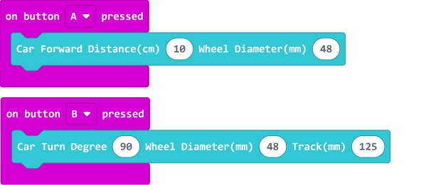
Sample Program:
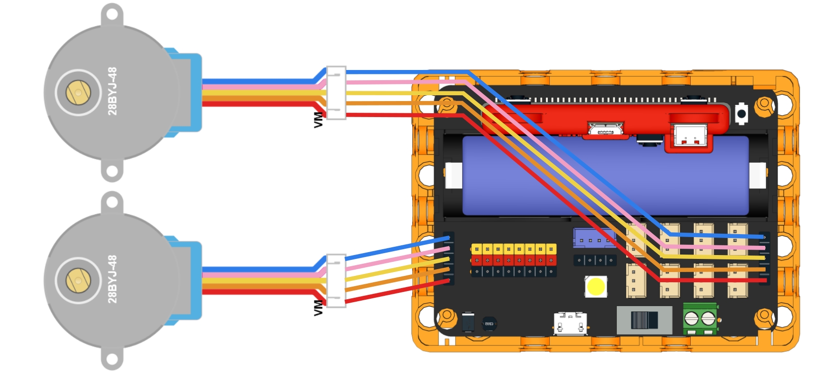
Connect Stepper Motors to the M1 and M2 port of the Robotbit Edu, with the red wire connecting to the VM port.
4. Programming the built-in LED strip
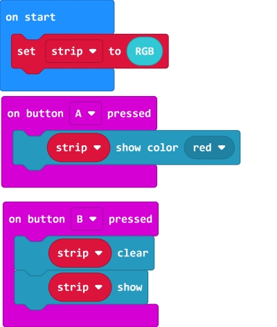
The programming blocks for the LED strip are found in the Neopixel tab.
4.1 Lighting up all lights
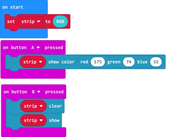
4.2 Customizing color with RGB
4.3 Customizing color with HSL.
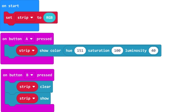
4.4 Lighting up individual lights
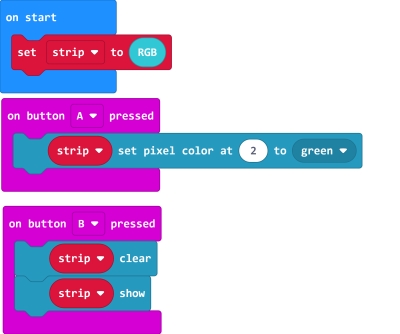
4.5 Adjusting the brightness.
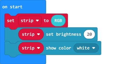
5. Programming the IO Pins
The blocks for the IO pins are found in the Pins tab.

5.1 Reading values from pins
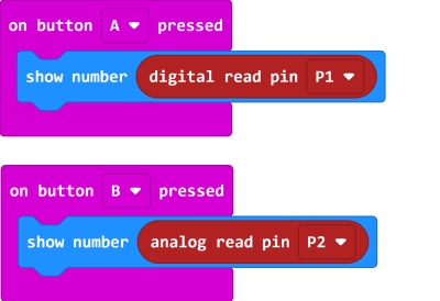
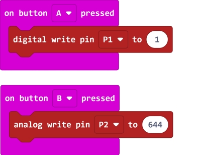
5.2 Writing values to pins
Last updated